Technical Details
Layout
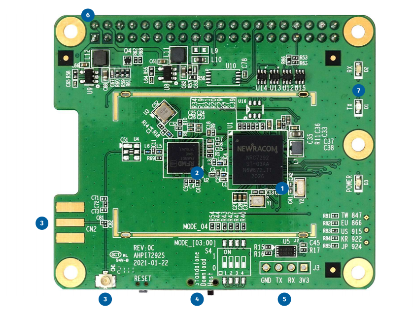
- Newracom™ NRC7292 WiFi HaLow™ SoC (IEEE 802.11ah draft 8.0 compliant)
- Qorvo™ RFFM6901 front-end
- IPEX/U.FL antenna connector
- Switch for NRC7292 mode selection
- 4-pin UART header (2.54 mm pitch)
- Raspberry Pi™ HAT form factor with 40-pin GPIO connector
- 3× LEDs
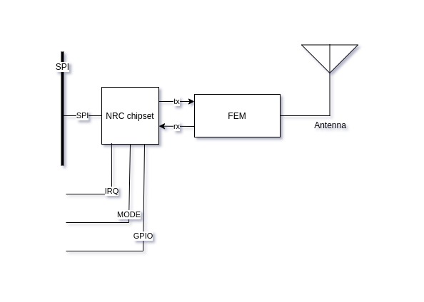
Block diagram
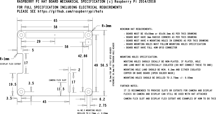
Dimension
Pinout
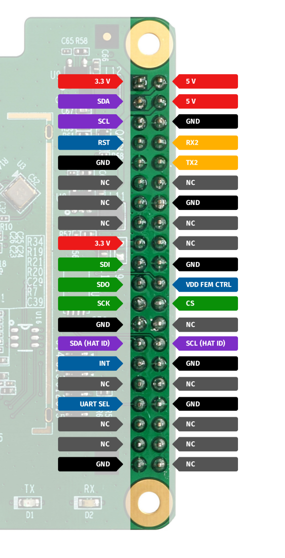
General
| Pin Number | Pin Name | Description |
|---|---|---|
| 1,17 | 3.3V | Reserved for future use indesigns based on 3.3 V power supply. (current module design is based on 5V power supply) |
| 2,4 | 5V | 5V DC power |
| 6,9,14,20,25,30,34,39 | GND | Ground |
| 11,12,13,15,16,18,26,31,32,35,36,37,38,40 | NC | No connection |
SPI
| Pin Number | Pin Name | Description |
|---|---|---|
| 19 | SDI | SPI data input |
| 21 | SDO | SPI data output |
| 23 | SCK | SPI clock |
| 24 | CS | SPI chip select |
Note
NRC7292 only supports mode SPI_MODE_0(CPOL 0, CPAH 0). For more information, please go to the official document: UG-7292-002-Host driver porting.pdf
I²C
| Pin Number | Pin Name | Description |
|---|---|---|
| 3 | SDA | I²C data |
| 5 | SCL | I²C clock |
| 27 | SDA(HAT ID) | I²C data, for PiHAT ID EEPROM |
| 28 | SCL(HAT ID) | I²C clock, for PiHAT ID EEPROM |
Note
The SDA(HAT ID) and SCL(HAT ID) are dedicated pins for PiHAT's ID EEPROM usage.
For more details, please go to the Raspberry Pi's document here: ADD-ON BOARDS AND HATs
Note
This ID EEPROM contains a machine-readable description of the HAT hardware in a form that allows the Pi to automatically configure the GPIOs and load appropriate device drivers. Ref: https://pihat.readthedocs.io/en/latest/
UART
| Pin Number | Pin Name | Description |
|---|---|---|
| 8 | RX2 | NRC7292's UART2 RX (See UARTs) |
| 10 | TX2 | NRC7292's UART2 TX (See UARTs) |
Others
| Pin Number | Pin Name | Description |
|---|---|---|
| 7 | RST | System reset (Preservered circuit, disable for now). PM_RESET is triggered by reset button for now |
| 22 | VDD FEM CTRL | Control RF frontend power. If VDD_FEM_CTRL=0, VDD_FEM=3.3V If VDD_FEM_CTRL=1, VDD_FEM=4V |
| 29 | INT | Interrupt, for NRC7292's SPI_EIRQ |
| 33 | UART SEL | GPIO for switching UART ports. (See UARTs) (NOTE: since R0B) |
Note
In the 1.3 Hardware components(page 8) section of document UG-7292-002-Host driver porting.pdf describes hardware GPIOs and pinout mappings.
LED
| Label name | Description |
|---|---|
| POWER | When the module is powered up, this GREEN led turns on |
| TX | ORANGE led, controlled by GPIO |
| RX | RED led, controlled by GPIO |
GPIO
| NRC7292 GPIO # | Default | Pin Number | Description |
|---|---|---|---|
| 02 | UART2 RTS , connected to LED:TX | ||
| 03 | UART2 CTS , connected to LED:RX | ||
| 16 | 5 | I²C SCL | |
| 17 | 3 | I²C SDA | |
| 25 | IN, HIGH | 22 | VDD_FEM_CTRL |
| 30 | SDA , connect to an onboard temp sensor IC(label:U6) | ||
| 31 | SCL , connect to an onboard temp sensor IC(label:U6) |
Note
Known NRC7292 GPIO's range is [0..31]
UARTs
NRC7292 has 4 UART channels. We have two available in this PiHAT device.
| NRC7292 defines | AHPI7292S | Description | Position |
|---|---|---|---|
| UART0 | Undefined | ||
| UART1 | Undefined | ||
| UART2 | RX2, TX2 | available for STANDALONE MODE | 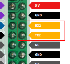 |
| UART3 | 4-pin UART header | for DOWNLOAD MODE use | 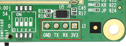 |
UART port switching with "UART SEL" GPIO
The TX,RX in PiHAT pinouts and 4-pin UART header can be swapped in specific conditions below:
| Mode switch state | GPIO of UART SEL |
|---|---|
| Host mode | OUT, HIGH(1) |
| Standalone mode | OUT, HIGH(1) |
| Download mode | OUT, HIGH(1) or IN |
This UART port switching mechanism make it possible to reflash firmware without manual 4-pin UART header wirings.
Revisions
Comparsion:
| R0A | R0B | R0C | |
|---|---|---|---|
| Mode switch | DIP switch | Slide switch | Slide switch |
| RF connector | IPEX (CN1) | SMA (CN1) IPEX (CN2) |
IPEX (CN1) SMA (CN2) |
| UART SEL | undefined | defined | defined |
| UART3 label | TX3,RX3 |
TX3,RX3 |
TX,RX |
Differences:
| Before | After | Notes |
|---|---|---|
R0A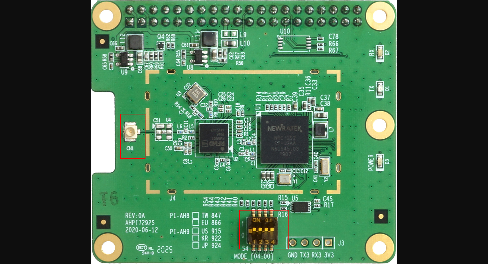 |
R0B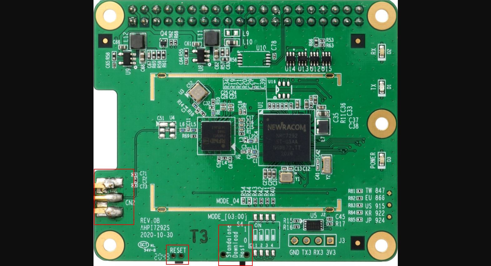 |
RF connector change position. Mode swith change from DIP switch to slide switch. Add reset button |
R0B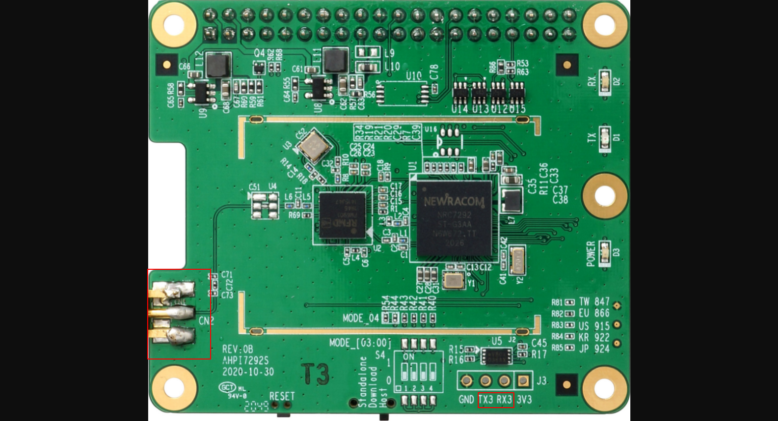 |
R0C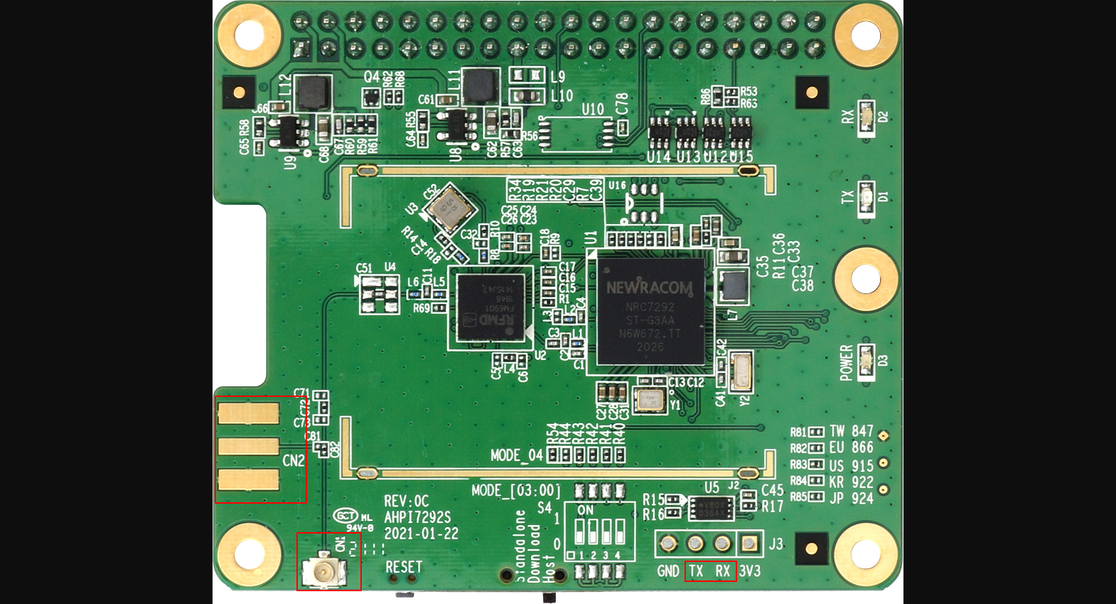 |
RF connector change position.TX3,RX3 change to TX,RX |
Mode
NRC7292 has 3 modes: HOST MODE, STANDALONE MODE, and DOWNLOAD MODE
HOST MODE
In this mode, the target device will act as a SPI slave device. The host device (ex: Raspberry Pi) need a proper driver to bring it up and controll it.
STANDALONE MODE
In this mode, the target device doesn't need external drivers. It will be up and running by itself while power on. Since it's self-running device, it required a built-in firmware to define its routines and behaviors.
Other devices can talk to this device throungh a UART interface, send commands and receives data with it.
DOWNLOAD MODE
This mode is for developers to upload firmware to this target device, so that it can be properly running in STANDALONE MODE.
There is an official document introduce how to utilize this mode, please see reference below:
Note
For more details, please read the upstream document UG-7292-004-Standalone SDK.pdf , page 18, chapter of "3 How to download compiled binaries"
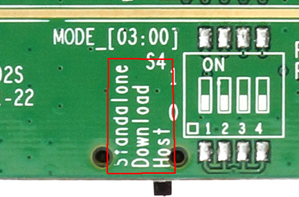
How to switch modes
For revision R0B, R0C:
New revisions are using slide switches:
For revision R0A:
The R0A revision use a DIP switch to switch modes:
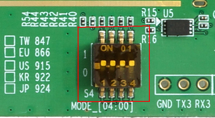
| Mode | Mode_03 ... Mode_00 | |
|---|---|---|
| Host mode | [0,0,0,1] | 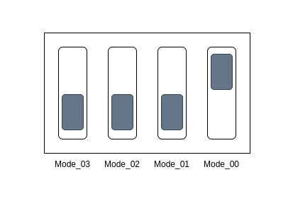 |
| Standalone mode | [0,1,0,0] | 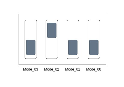 |
| Download mode | [0,0,1,1] | 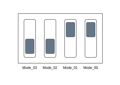 |